DDS(VFO) drive PLL for 144MHz |
Ten years ago, i started to find a solution regarding local oscillator for 2m SSB transceiver. Due hard access to suitable rf components, VCO 133,3-135,3MHz (FI=10,7MHz) controlled by a VFO-PLL was the last solution. FET Hartley VFO 3,3-5,3MHz was used in 2006. Unfortunately i didn't succeed to build a very stable VFO (poor variable capacitor). Now in 2016 is easier to replace the VFO with a cheap DDS. AD9850/AD9851/AD9834 are good candidates to generate a stable signal between 3,300000 - 5,300000MHz, 1Hz step. In this way PLL will be drived by DDS. On the Internet is easy to find a simple DDS oscillator together with uC controller (maybe Arduino). Of course, frequency display needs to be corrected by IF value, but is possible to make 2m QSO without using shift IF. DL4JAL has a excellent all band DDS PIC controller.
Idea for this PLL comes from Kenwood TR9130 Service Manual, nice 2m transceiver used by YO4GJH during VHF contests in my QTH locator (10 years ago).
Short description of DDS(VFO) drive PLL:
133,3-135,3MHz VCO signal (local oscillator) is mixed with a stable 130MHz signal. The difference signal 3,3-5,3MHz is filtered and amplified. CMOS IC 4046 compare the phase-frequency of this signal with DDS (VFO) signal. Error signal (tuning voltage) is filtered using one active low pass filter. VCO is controlled by error voltage (closed loop). Hereby is possible to obtain a very stable VHF signal, same stability like DDS.
13MHz quart oscillator is 10 times multiplied using BB139 varicap diode (or other type). 130MHz band pass filter must to be exactly tuned, otherwise is possible to select a wrong harmonic. The space between two harmonic signals is only 13MHz. Bandpass coupling capacitor has only 0,2pF and is made by twisting 2 isolated wires (0,3-0,5mm), lenght 5mm.
Advice: Good quality 13MHz crystals are frequently used in GSM phones (master clock). Try to find one old cellular phone.
Frequency of crystal is adjusted during RX period using RIT control circuit. RIT circuit is useful when classic VFO is used. For DDS, the RIT control is made by software.
Optimum level for BFX89 mixer is possible to require some adjustments in order to obtain clean IF 3,3-5,3MHz signal, aprox. 3Vpp measured between BF115 amplifiers and 4001(4011) gate. Use one 10MHz oscilloscope to measure the signals.
VCO signal is generated by a Colppits oscillator. Signal is buffered, amplified and band pass filtered. VCO signal is ready to be connected with rx-tx 144MHz mixers.
All frequencies were calculated for 10,7MHz SSB filter. Is possible to use other FI values. In this situation, DDS (VFO) and VCO have other frequencies.
VCO = (144...146MHz) - FI
DDS(VFO) = VCO - 130MHz
All adjustable coils use 4,5mm plastic support, VHF ferrite core (violet) and 0,3-0,4mm wire. For some coils i remember only the inductance (nH), i forgot how many turns was used for middle position of the ferrite core. Check the frequency resonance with a grid-dipmeter, rf generator/rf voltmeter or VHF VNA.
![]()
![]() DDS(VFO) drive PLL 4046
DDS(VFO) drive PLL 4046
![]() VCO 133,3-135,3MHz
VCO 133,3-135,3MHz
![]() RIT Control for VFO
RIT Control for VFO
PHOTOs
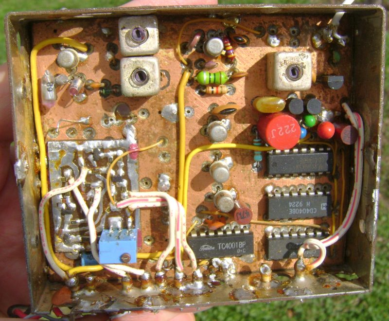
![]() VFO/PLL 4046
VFO/PLL 4046
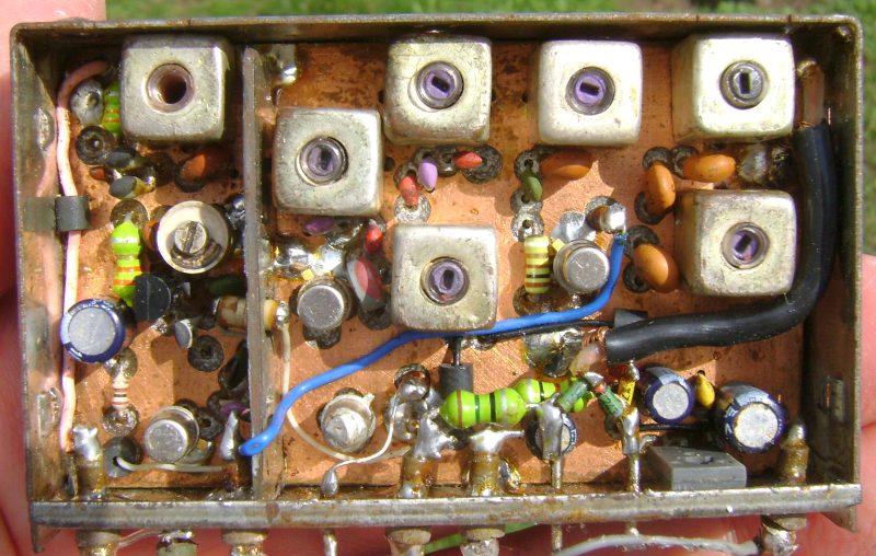
![]() VCO 133-135MHz
VCO 133-135MHz